- Appearance design patent certificate of “Color Assessment Cabinets”.
- “HARUCN” trademark registration success, start a new journey of the brand
- Successful registration of “Huaruchang” trademark
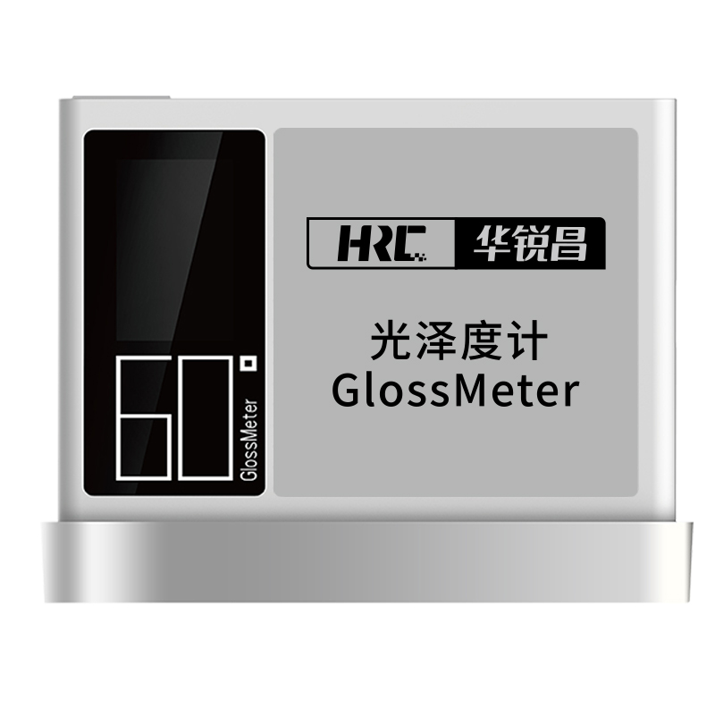
- “Certificate of Design Patent of “Glossiness Meter
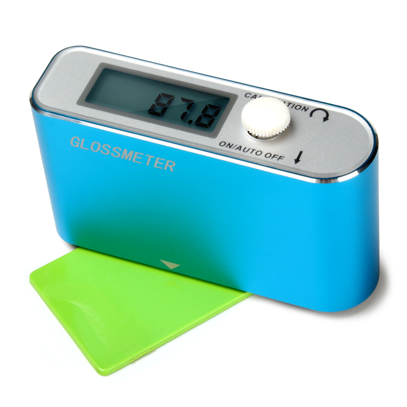
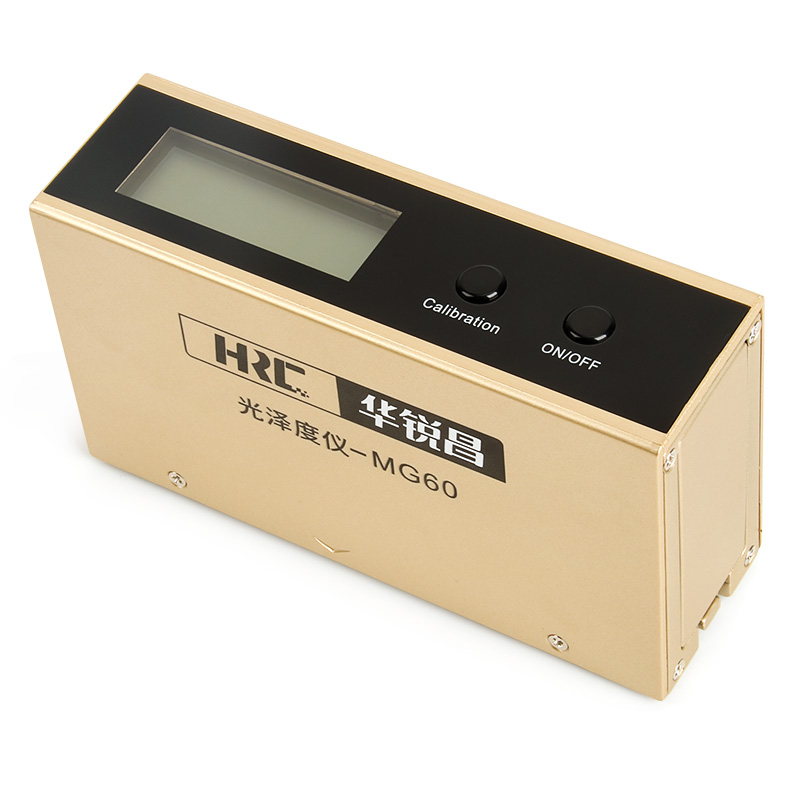
- Glossmeter Selection and Measurement Principle
- The new “MG6 Series Glossmeter” shocking debut
E-mail:hrc@hrckeji.com
Phone:18928463858
TEL:400-968-6558
Address:F3-002, Zhonghuiyuan Internet Creative Park, No. 1 Huangtian Road, Hangcheng Street, Bao'an District, Shenzhen, Guangdong
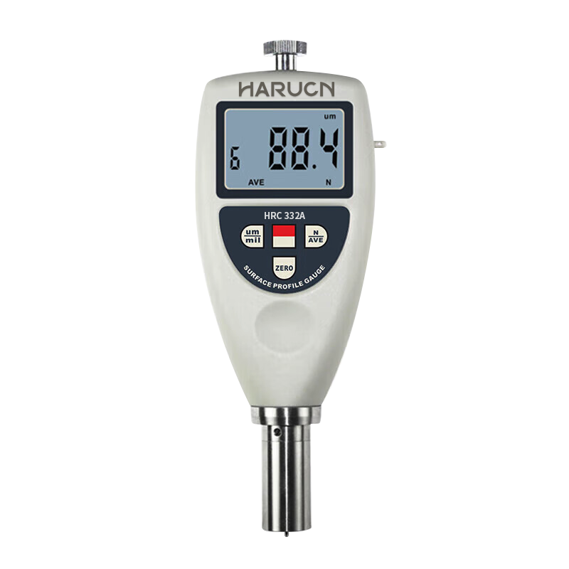
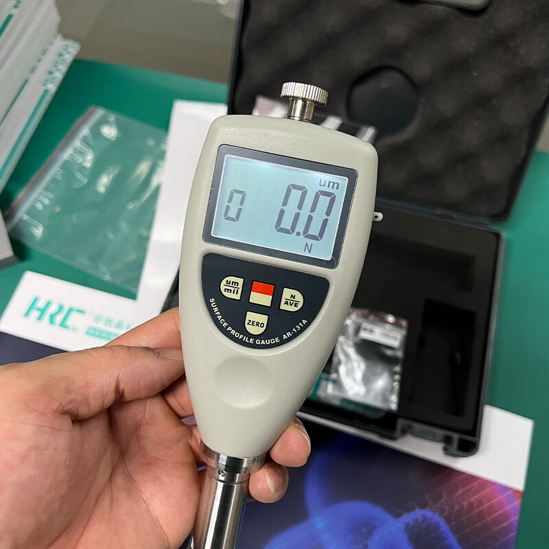
HRC332A sand blasting and shot blasting roughness meter, small size and light weight, easy to carry and convenient to use.
Abrasive Blast Roughness Tester HRC332A, this abrasive blast roughness tester is small in size, light in weight and easy to carry, convenient to use and operate, * Conforms to ASTMD4417-B, IMOMSC215(82), SANS5772, US Navy NSI009-32, US Navy PPI 63101-000. test method, can measure the height of peaks and valleys of the surface directly. The height of the peaks and valleys of the
I. Product Characteristics
Suitable for: shot blasting industry, printing industry, spraying anti-corrosion industry and other surface roughness needs of the industry to use, according to the selected measurement conditions to calculate the coresponding parameters, in the LCD display clearly shows all the measurement parameters.
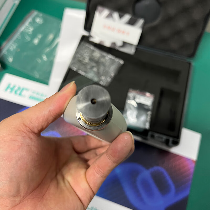
* Measurement of the surface roughness of the workpiece, the instrument sensor placed on the surface of the workpiece to be measured by the instrument built-in sharp stylus feel the roughness of the surface to be measured, the roughness of the surface of the workpiece to be measured at this time caused by the stylus to produce displacement, the displacement of the sensor inductance of the inductive coil of the inductance of the sensor to change, so that in the output of the phase-sensitive rectifier to produce and the surface roughness of the surface to be measured proportional to the analog signal, the signal is amplified and level converted into the data acquisition system. After the signal is amplified and level converted into the data acquisition system, the DSP chip will collect the data for digital filtering and parameter calculations, the measurement results in the LCD display, and at the same time can be communicated with the computer to achieve data analysis, statistics and printing.
* High-precision inductive sensor
* Manual shutdown and automatic shutdown
* With metric/imperial conversion function
* Average value calculation function
* Uses USB cable output and RS-232 cable output for data connection to a computer.
* Bluetooth™ data output option available
II. Product Parameters
Display: LCD display
Accuracy: ±5% or ±5um
Resolution: 0.1μm (measured value <100μm) 1μm (measured value >100μm)
Measuring range: 0~750um
Measuring principle: Inductive
Operating environment: Temperature 0~50°C (32~122°F), Humidity <80%RH
Power supply: 2x1.5vAAA No. 7 battery
Size: 176x63x25mm, 6.9x2.5x1.0inch
Net weight: 310g (without battery) 10.93oz
Standard accessories: main unit, calibration block, carrying case, instruction manual
Optional Accessories:* USB cable output,* Bluetooth™ data output, and
Panel Description
| 3-1 Display 3-2 Actual Measurement Count Indication 3-3 Average value indicator AVE 3-4 RS-232C Interface 3-5 Metric/Imperial Unit Conversion Key 3-6 Zero Setting Button 3-7 Battery Cover 3-8 Wrist Strap Clip 3-9 Measurement Count/Average Setting Value Button 3-10 Switch Button 3-11 Pressure pin |
")
IV. Measurement Parameters
4.1 After the preparation work is done, if the measurement conditions do not need to be changed, the measurement will start and the measured value will be shown on the display.
4.2 Tap the power button to turn on the power of the whole machine.
4.3 Place the instrument vertically on the object to be measured, let the end face of the pressure needle and the specimen tightly in contact for 1 to 2 seconds, so that the measured value will automatically be displayed on the LCD. (Special attention: the stylus of the instrument should not exceed the edge of the surface to be measured).
4.4 Averaging Function and Measurement Count Setting Press the 'N/AVE' key and the screen displays the set count indication and the number of measurements. Continue to press the 'N/AVE' key to set the number of measurements, the maximum value of the number of measurements is 9. When the number of measurements has been set, the 'ZERO' key can be pressed to return to the measurement state. After each test, the instrument will simultaneously display the coarse exceeding value of this test and the number of tests, when the set number of tests is reached, it will first display the coarse exceeding value of this test, and then display the average value, and at the same time, it will display the symbol of the average value, 'AVE', and there will be two buzzers sounding. Users can also record the data of several measurements according to the need, and then manually calculate the arithmetic average value. After setting the number of measurements, press the 'ZERO' key to return to the measurement state, or the machine will automatically enter the test state after a few seconds.
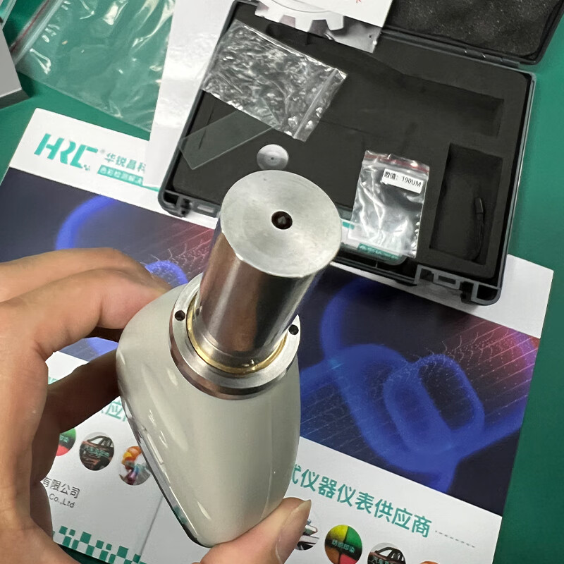
V. Calibrate the instrument
Zero calibration, first put the glass zero plate on the desktop, hold the instrument vertically, press the instrument probe on the glass zero plate, do not let go, at this time, the reading on the display should be zero, otherwise, it should be calibrated zero. Otherwise, the display should be calibrated to zero, i.e., lightly press the 'ZERO' key to make the reading on the display zero.
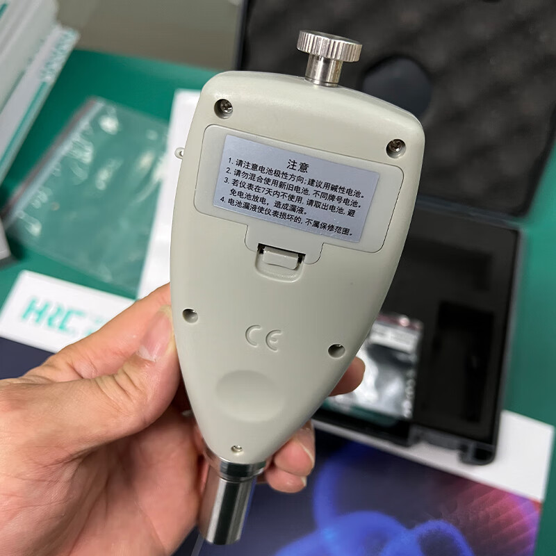
VI. Battery Replacement
6.1 When the battery symbol will appear on the display, the battery needs to be replaced. Open the battery cover and remove the batteries.
6.2 Install the batteries correctly as shown on the label on the battery compartment.
6.3 If the instrument will not be used for a long period of time, remove the batteries to prevent them from rotting and damaging the instrument.
Computer Connection
7.1 The optional “USB Cable Output”, “RS232C Cable Output” and “Bluetooth™ Data Output” can be used to connect to a PC computer as shown on the label on the battery compartment. The optional “USB Cable Output”, “RS232C Cable Output” and “Bluetooth Bluetooth™ Data Output” can be used to communicate with a PC for data acquisition, processing, analysis and printing.
7.2 Plug the RS-232 connection cable into the corresponding hole of the instrument
7.3 Connect the RS-232 cable to the instrument.
7.4 Open the software on the operating platform and select COM port in the system settings.
7.5 Click the data collection button, and then click the start/continue button.
Maintenance and care of the instrument
Avoid collision, violent vibration, dust, humidity, oil, strong magnetic field, etc.; the sensor is a precision part of the instrument and should be carefully protected. After each use, the sensor should be put back into the packing box; the random standard sample plate should be carefully protected to avoid scratches caused by the calibration instrument error.